Adjustable timer circuit using 555 How does ne555 timer circuit works Timer circuit diagram minute delay wiring time relay 555 using monostable 15 circuits ic electronics circuitdigest simple 55 seconds electronic
12 Hour Timer Circuit Diagram
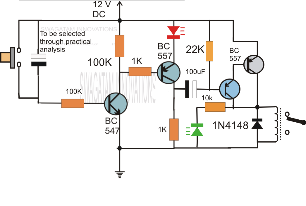
Simple delay timer circuits explained – homemade circuit projects Simple long duration timer Delay timer circuits circuit simple electronic explained diagram projects homemade trigger electronics step seconds two schematics few sequential long active
Diagram led chaser 4017 555 capacitor circuit timer using wiring counter motor run start off ic phase electrosome shut mechanical
555 timer diagram internal ic astable circuit multivibrator monostable bistable modeSimple delay timer circuits explained 0 to 99 counter circuit using 555 timer and cd4033 icInductor-based astable 555 timer circuit.
Simple circuit diagram using 555 timerDancing light using 555 timer 4017 ve 555 entegreli ayarlanabilir 10'lu led yürüyen işık devresi veTime delay relay circuit using 555 timer ic.

12 hour timer circuit diagram
Delay relay circuit diagramTimer circuit diagram Timer delay relay 555 proteus pcb simulation1 minute timer circuit diagram.
Time delay relay using 555 timer, proteus simulation and pcb designAdjustable 555 timer circuit Circuits delay circuito atraso sequential555 timer circuit using light dancing circuits diagram easyeda chip pcb pulse 555timer ne555 projects electronics time astable lm555 mode.

Timer circuit diagram circuits electronics fridge schematics working principle ic elprocus time electronic long electrical duration
Timer delay eleccircuit circuits relay transistor555 timer circuits pdf Delay circuits circuit timer relay electronic sequence arduino sirkuit sequential alarm transistors pressed schematicsSimple delay timer circuits explained.
Time delay circuit diagramWhat everybody ought to know about the 555 timer Types of timer circuits with schematics and its working principle555 timer schematic / led chaser using 4017 counter and 555 timer / the.

Timer 555 circuit diagram schematic ne555 datasheet discrete kit pinout block does circuits transistor works eleccircuit integrated functional pins connection
555 timer circuit electronic circuits metronome ought everybody know components return online555 timer ic pin diagram features and applications .
.


555 Timer Schematic / LED Chaser using 4017 Counter and 555 Timer / The

Simple long duration timer - ElecCircuit.com | Basic electronic

Simple Delay Timer Circuits Explained | Homemade Circuit Projects
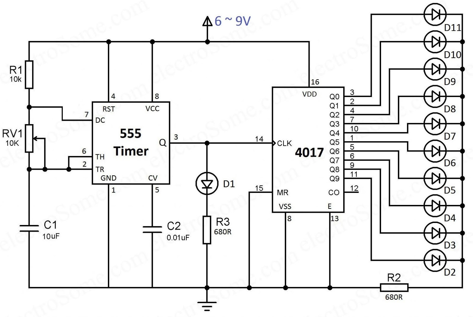
4017 ve 555 Entegreli Ayarlanabilir 10'lu LED Yürüyen Işık Devresi ve

Simple Circuit Diagram Using 555 Timer
12 Hour Timer Circuit Diagram

Adjustable 555 Timer Circuit

Time Delay Circuit Diagram
